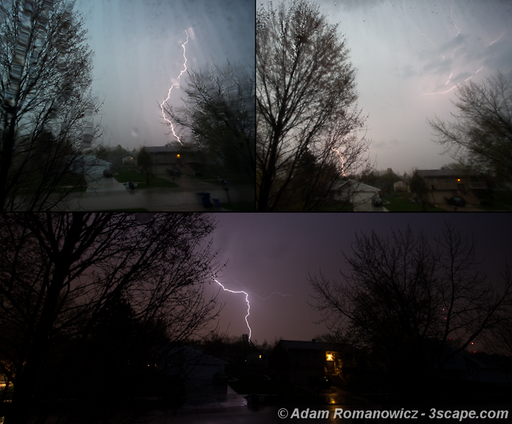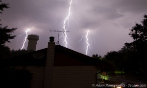
For some time now, I’ve been looking for a better way to capture incredible lightning photos other than pushing the shutter button over and over hoping to catch a bolt. The image on the left was a 15-second exposure that luckily captured two lightning bolts in the same frame. The third bolt was added from a second frame a few minutes later.
Some commercial lightning triggers are available if you’re willing to part with a few hundred dollars, which I was not, for an experimental endeavor. So I started researching homebrew solutions that would allow me to tinker while also saving a bunch of money. Enter: Arduino – a powerful open-source prototyping platform utilizing ATmega programmable microcontrollers.
At this point, I would like to thank Maurice Ribble for his incredible work on the original iteration of this shutter trigger, which over the last few years he has developed into a full-blown automatic triggering solution using any number of inputs including light, laser, sound, or motion, known as Camera Axe (doesn’t seem available anymore).
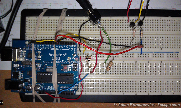
That all said, I didn’t need high-speed flash/camera triggers for photographing things blowing up (although it sounds like a lot of fun), or the tons of features and options of the Camera Axe. However, I did want a solution versatile enough to modify or add on to later, if I wanted. So I bought an Arduino UNO board with an ATmega328, dusted off my old breadboard, and started experimenting with a few components. In the end, I ended up with a circuit based on Maurice’s original design, but incorporating some of the tweaks from his newer circuits, and an optimized version of code. The details below show how you can make your own. Note that mine is based on inputs for my Canon 40D Canon 5D Mark III Canon EOS R5 😲.
Circuits
There are three parts to the circuitry for this project. First and foremost, the microcontroller mentioned above, which runs the code and powers the inputs and outputs. Second, we need a sensor for detecting lightning flashes. Finally, we need the shutter trigger mechanism.

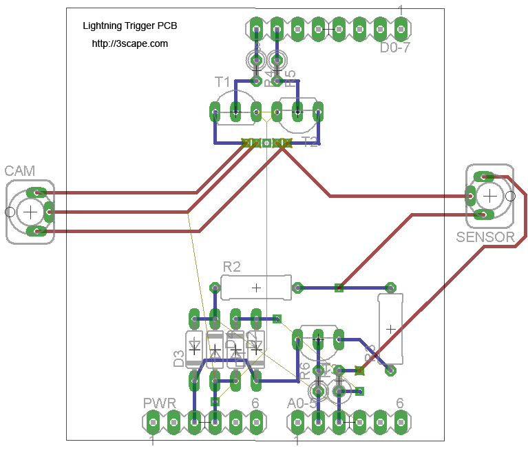
The circuits on the left show the input and output interfaces as they connect to the Arduino. For added flexibility, instead of hardwiring everything, I decided to use 3.5mm stereo jacks for the sensor input and camera output. This way, I can later connect different sensors for high-speed photography without rebuilding the circuit board.
The input circuit provides 5V power to the sensor port, which in this case goes to a phototransistor. The phototransistor detects light at time intervals determined by the programming and clocking of the processor. When the light level changes from one interval to the next, there is a change in the voltage level which is detected on the analog port of the Arduino. Programming says “if the change is more than X threshold, trigger the camera”.
A signal is then sent to one of the Arduino’s digital ports, changing that port’s voltage from a low (off) state to a high (on) state. The transistors on the output circuit act as solid-state switches, which just mimic the mechanical switch of a tethered camera remote (cable release). At this point, the digital output port is put back into low (off) state, and the light detecting loop continues.
The circuit shown here was done using Eagle (now an Autodesk product).
Parts List
I bought most of the parts I needed from Jameco Electronics, they have everything you might need and more, just be sure to buy a decent amount of stuff, otherwise, it doesn’t really work out well on shipping. Outside of the list below, you’ll need some copper-clad prototyping board, a power switch, and a plastic project enclosure to stuff it all in. And of course, this is based on the Arduino UNO, but other Arduino-based boards should work also.
| Part ID | Part# / Description |
| PT | SFH 309-5 OSRAM Phototransistor |
| D1-D4 | 1N5819 Schottky Diodes (1N4148 are ok also, not quite as fast) |
| R1-R2 | 150 ohm 1/4 W Resistors |
| R3 | 30 ohm 1W Resistor |
| R4-R5 | 10k ohm 1/4W Resistors |
| R6 | 1k ohm 1/4W Resistor |
| R7-R8 | 10k ohm 1/4W Resistors |
| T1-T2 | 2N2222 NPN Transistors |
| T3 | 2N3906 PNP Transistor |
| A0/D0 | Pin Headers |
| n/a | 3.5mm Stereo Jacks (2) |
| n/a | 9V Battery holder / contacts |
Code
The programming code for this is really basic and is written using Arduino IDE. The code below is optimized to read and modify ports directly, rather than using functions to do so. While this isn’t recommended from a readability perspective, it shaves some precious time off each loop as the code runs. Precious time, you ask? A lightning strike on average lasts about 100ms. The shutter lag for my camera, the Canon EOS R5 is about 50ms in EFCS mode (61ms for 5D Mk3, and 59ms for Canon 40D). Add another few ms for the program to run, and there’s not that much spare time to capture a bolt in the frame. So if I can get the code from milliseconds down to microseconds, it can make a difference. The code is shown below, commented to show what’s really happening.
#define SENSOR1_POWER_PIN     15    // Analog output pin A1
#define SENSOR1_APIN           2    // Analog input pin A2

// Inline AVR Assembler code
// cbi and sbi are standard (AVR) methods for setting,
// or clearing, bits in PORT (and other) variables.
#ifndef cbi   // clear
#define cbi(sfr, bit) (_SFR_BYTE(sfr) &= ~_BV(bit))
#endif
#ifndef sbi   // set
#define sbi(sfr, bit) (_SFR_BYTE(sfr) |= _BV(bit))
#endif

int last_loop_light = 0;
int this_loop_light = 0;
int threshold = 10;      // light change threshold

void setup()
{
  pinMode(SENSOR1_POWER_PIN, OUTPUT);    // pinmode for powering sensor
  digitalWrite(SENSOR1_POWER_PIN, LOW);  // set transistor base to LOW to switch power on

  // Serial.begin(9600);  // uncomment for debugging

  // The ADPS are the bits to determine the division factor between the system
  // clock frequency and the input clock to the AD converter.
  // Below, setting to 100 sets division factor to 16 (speed of AD conversion)

  sbi(ADCSRA,ADPS2) ;    // Set ADCSRA register, bit 2 (ADPS2) to 1
  cbi(ADCSRA,ADPS1) ;    // Set ADCSRA register, bit 1 (ADPS1) to 0
  cbi(ADCSRA,ADPS0) ;    // Set ADCSRA register, bit 0 (ADPS0) to 0

  // Bitwise copy DDRB register settings to DDRD, making sure that bit 7 is 1
  // This ensures pin 7 is set to OUTPUT mode
  DDRD = DDRB | B10000000;

  // initialize digital pins 0-7 low
  PORTD = B00000000;

  last_loop_light = analogRead(SENSOR1_APIN);  // read initial light level
}

void loop() {

  this_loop_light = analogRead(SENSOR1_APIN);  // read light level

  if ((this_loop_light - last_loop_light) > threshold) // compare light levels
  {
    // Manipulating registers/pins directly is much faster than using functions
    PORTD=B10000000; // set pin 7 high (trigger camera)
    delay(100);      // wait 100ms
    PORTD=B00000000; // set pin 7 low (reset trigger)

    // uncomment following for debugging:
    // Serial.print("old:");
    // Serial.print(last_loop_light,DEC);
    // Serial.print(", new:");
    // Serial.println(this_loop_light,DEC);
  }

  last_loop_light = this_loop_light;  // set current light level
}
Build
The only thing left to do now is building it! There are a few ways of putting together a circuit board, by either positioning and wiring components on a solderless protoboard, using a protoboard with solder points, as I did in this case, or etch your own copper clad PCB. There are also companies that specialize in PCB creation, such as Batch PCB. However, it can take many weeks to get a board, and if it ends up being a bad design you need to start all over.
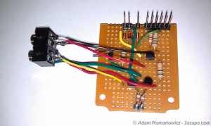
The circuit board above was designed as an Arduino “shield” or daughter card, that is placed on top of the UNO board, directly interfacing using the header pins. Alternatively, you can use the UNO board to program the microcontroller, and build a more elaborate circuit around that so everything is on a single board. Since I wanted to use my Arduino board for more things in the future, I opted for the shield design.
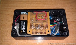
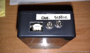
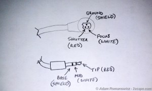
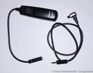
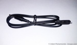
Stuff the completed circuit board into an enclosure (in which you’ll have to cut/drill some holes for interface ports), wire up the battery and power switch, and you’re finished! Since I wanted programming access to the Arduino board without having to open the box, I cut a hole for the USB port. The USB port on the Arduino board can also be used with external power, in case you don’t want to use the 9V battery. I also mounted the 3.5mm stereo jacks on the same side so all of my cables are on one side. Speaking of cables, that’s what needs to be made to interface with the camera. The R5, along with many other Canon cameras use a proprietary N3 connector. I cut my Canon RS-80N3 cable release in half, and attached 3.5mm stereo jack and plug on the ends so that I can still use my remote while optionally using the N3 connector for the lightning trigger.
Lastly, assemble the light sensor per the circuit design previously shown. The phototransistor and resistors can be hard-wired and soldered together, or for a cleaner look, can be mounted to a tiny PCB. This is what I did and then protected the PCB with heat shrink tubing.
Shoot!
Time to get out and test the rig. Perhaps in the near future, I’ll write up a tutorial on night and lightning photography, but in the meantime, here’s the quick and dirty. For my initial tests, I set my camera to manual f/8 for 10 seconds at ISO 100, based on metering the night scene. As night turned to day, I changed my camera to Aperture Priority mode, still at f/8 and ISO 100. The first storm of the spring season produced the results here: